Hi all.
This has been my project for the last few days, and Ive finally cracked it, so Im happy to share it with you. Aeroponic timers are expensive, but relitavely simple and cheap devices to the amateur electronics geek. This adjustable timer turns a pump ON for 7-27 seconds, and OFF for 20seconds 4 minutes. The times could be easily changed longer or shorter by using different value potentiometers. The components cost me under £15 but I did buy a 12v transformer as well. You dont have to use 12v DC for the circuitry, you could use a 9v battery with different components. However I opted for mains power because I didnt want batteries running out on me. I havent touched any electronics for over 10 years when I did my apprenticeship in manufacturing engineering, but I managed - so its not rocket science.
DISCLAIMER The following timer is a device that uses mains voltage. Although safe to use, in replicating this device, any mistakes in wiring could lead to electric shock with mains power. This guide is for information only. The following timer could be made to work with a safer 12v DC water pump, but would require different components from the ones specified. (just dont do it if you dont know what youre doing, stoned or drunk. Check all circuitry using multimeters or LEDs before attaching mains power!)
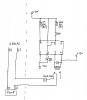
What were making is a Timer circuit that controls a relay switch that switches a water pump ON and OFF to an adjustable timeframe.
Components:
555 Timer chip + mount
Potentiometer 1M ohm
Potentiometer 100k ohm
Resistor 33k ohm
Capacitor 330uF
Silicon Diode 1amp
Solid State Relay 12v / 240v (or 110v)
12v DC transformer
Box
Circuit Board
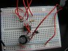
I also used a double plug socket, so that I can use 2 pumps on the same timer. I also used a bread board type circuit board to test the circuit before soldering. I also used an LED to make sure the circuit was working. ( I would rather use an LED instead of a relay to make sure everything is working, I only connected the relay and mains power when I was 100% sure the circuit was working. Using a multimeter to check as well.
STEP 1.
Assemble components on a bread board type circuit board (see photo). In the final build when the timer is ON there will be 10v between pin 3 and pin 4 of the chip. This is where we will connect the coil of the relay. (A relay is an electronic switch, when a small current is passed through it will switch a higher voltage switch) In order to check the circuit, use an LED between pin 3 and -12v terminal. (make sure LED and Diode are the correct way round, this had me stumped for ages). If the circuit is good, the LED should be ON for a long time and OFF for a short time.
STEP 2.
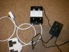
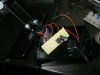
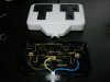
Check relay switch with a multimeter or circuit tester. Find out which way the switch goes when a 12v current is passed through it. For this build, we need the relay to turn OFF when a current is present. THE RELAY CONTROLS MAINS VOLTAGE!! Personally I prefer to not have the relay connected to the circuit board, its just asking for trouble. I connect the small 12v wires to one side of the relay, and the thicker mains wires to the other side. I then tape it up good and proper with electrical tape so that the Mains pins are never going to touch any of the small circuitry or the box edges, my hands etc. (see photo of taped up relay)
STEP 3.
Once happy that everything is working and safe, solder onto circuit board and trim the board to fit in the box. I prefer to tape any exposed wires with tape, so as to not short circuit anything when box is assembled.
STEP 4.
Drill holes in the box for the potentiometers (pots) and wires, solder pots onto circuit. Again, because circuit has been re-built, I will check the circuit works by checking the current at the relay switch with a multimeter. Only once I am satisfied with this will I plug in the mains. Assemble everything in the box, check again.
There you have it! To further improve the timer, I added a photoresistor in series to the pot controlling the OFF time. This pushed the OFF time up to 7-8 mins when its dark, instead of 4 mins in light. Also, you could add a thermistor to the ON pot, to lengthen the ON time when it is hotter and your plants need more water.
Enjoy!
I'm not a master of electronics, so please don't ask complicated questions. I came up with timings through trial and error with different value resistors. Hope you manage to make something similar! and stay safe!!
")
This has been my project for the last few days, and Ive finally cracked it, so Im happy to share it with you. Aeroponic timers are expensive, but relitavely simple and cheap devices to the amateur electronics geek. This adjustable timer turns a pump ON for 7-27 seconds, and OFF for 20seconds 4 minutes. The times could be easily changed longer or shorter by using different value potentiometers. The components cost me under £15 but I did buy a 12v transformer as well. You dont have to use 12v DC for the circuitry, you could use a 9v battery with different components. However I opted for mains power because I didnt want batteries running out on me. I havent touched any electronics for over 10 years when I did my apprenticeship in manufacturing engineering, but I managed - so its not rocket science.
DISCLAIMER The following timer is a device that uses mains voltage. Although safe to use, in replicating this device, any mistakes in wiring could lead to electric shock with mains power. This guide is for information only. The following timer could be made to work with a safer 12v DC water pump, but would require different components from the ones specified. (just dont do it if you dont know what youre doing, stoned or drunk. Check all circuitry using multimeters or LEDs before attaching mains power!)
What were making is a Timer circuit that controls a relay switch that switches a water pump ON and OFF to an adjustable timeframe.
Components:
555 Timer chip + mount
Potentiometer 1M ohm
Potentiometer 100k ohm
Resistor 33k ohm
Capacitor 330uF
Silicon Diode 1amp
Solid State Relay 12v / 240v (or 110v)
12v DC transformer
Box
Circuit Board
I also used a double plug socket, so that I can use 2 pumps on the same timer. I also used a bread board type circuit board to test the circuit before soldering. I also used an LED to make sure the circuit was working. ( I would rather use an LED instead of a relay to make sure everything is working, I only connected the relay and mains power when I was 100% sure the circuit was working. Using a multimeter to check as well.
STEP 1.
Assemble components on a bread board type circuit board (see photo). In the final build when the timer is ON there will be 10v between pin 3 and pin 4 of the chip. This is where we will connect the coil of the relay. (A relay is an electronic switch, when a small current is passed through it will switch a higher voltage switch) In order to check the circuit, use an LED between pin 3 and -12v terminal. (make sure LED and Diode are the correct way round, this had me stumped for ages). If the circuit is good, the LED should be ON for a long time and OFF for a short time.
STEP 2.
Check relay switch with a multimeter or circuit tester. Find out which way the switch goes when a 12v current is passed through it. For this build, we need the relay to turn OFF when a current is present. THE RELAY CONTROLS MAINS VOLTAGE!! Personally I prefer to not have the relay connected to the circuit board, its just asking for trouble. I connect the small 12v wires to one side of the relay, and the thicker mains wires to the other side. I then tape it up good and proper with electrical tape so that the Mains pins are never going to touch any of the small circuitry or the box edges, my hands etc. (see photo of taped up relay)
STEP 3.
Once happy that everything is working and safe, solder onto circuit board and trim the board to fit in the box. I prefer to tape any exposed wires with tape, so as to not short circuit anything when box is assembled.
STEP 4.
Drill holes in the box for the potentiometers (pots) and wires, solder pots onto circuit. Again, because circuit has been re-built, I will check the circuit works by checking the current at the relay switch with a multimeter. Only once I am satisfied with this will I plug in the mains. Assemble everything in the box, check again.
There you have it! To further improve the timer, I added a photoresistor in series to the pot controlling the OFF time. This pushed the OFF time up to 7-8 mins when its dark, instead of 4 mins in light. Also, you could add a thermistor to the ON pot, to lengthen the ON time when it is hotter and your plants need more water.
Enjoy!
I'm not a master of electronics, so please don't ask complicated questions. I came up with timings through trial and error with different value resistors. Hope you manage to make something similar! and stay safe!!
Attachments
-
 35.8 KB Views: 330
 -
 90.8 KB Views: 243
 -
 58.9 KB Views: 201
 -
 69.1 KB Views: 204
 -
 66.1 KB Views: 196
 -
 56.6 KB Views: 183
 -
 45.3 KB Views: 207