DIY COB temp logger and LCD display

_MrBelvedere_

Well-Known Member
Here are instructions to build a LCD display showing the temperature of your COBs. The temperature is read by a temperature sensor chip thermal pasted (or glued) directly to the COB board.


So the temperature is pretty accurate, it is not measuring the heatsink temperature, it is monitoring the COB directly. The temperature is taken every ten seconds and logs it to the pc.

This is just for a temporary test of everything- to help read temperatures. Obviously in a production room you don't need any of this- or if you want to have it, mount everything more secure and permanent.

Parts:
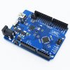
Arduino UNO R3 ($6)
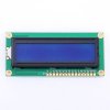
LCD Display model 1602 ($2)
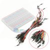
Breadboard Kit ($4.21) (has board and jumper wires)
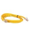
Ethernet cable ($2 )
3pin cpu fan connector (50 cents)

1x 5M ohm resistor (10 cents)
3x 220 ohm resistor (10 cents) (or 1x 1K ohm resistor)
3x DS18B120 Dallas temperator sensor chip ($1 apiece)

Part Pictures:
01 1602 lcd display (2).jpg

bbkit.jpg 1602 lcd display.jpg ethernet.jpg mb_fan_3pin.jpg resistor assorted.jpg s-l500.jpg


continued below...
 

Attachments

Last edited:

_MrBelvedere_

Well-Known Member
Assembly Instructions:


Wire the breadboard and Arduino like this:
IMG_0007.JPG

IMG_6460 (Medium).JPG

I put two extra DS18B20 temp sensors directly on the board just to make sure the program could handle multiple sensors easily. They can be plugged in and unplugged realtime and the program will still run fine without skipping a beat.

IMG_6461 (Medium).JPG


You can see above you need to cut the ends off of the Ethernet cable leaving only the blue, green, and orange wires. Snip the other ends off, they are not needed because the sensor chip only has three legs.


Plug the DS18B20 temp sensor 3 legs into the pc clip, or just attach the 3 ethernet wires to the chip legs with solder or whatever is easy. Make sure the connection is good.
IMG_6453 (Medium).JPG


Connect the thee wires to the ethernet cable using solder, twisting, or whatever you like. Make sure the wires are not touching and the connection is good. Snip off any exposed wires so they are not sticking out and the wires are isolated properly and not touching each other.
IMG_6455 (Medium).JPG

Mounting the sensor:

This is just for a temporary test of everything- to help read temperatures. Obviously in a production room you don't need any of this or if you want to have it, mount everything more secure and permanent.

Mount the COB with thermal paste or however you like. In the picture below you will see that I am using standard Aluminum U-Channel with some scuff marks... it is not a polished heatsink. It is an eight foot long U-Channel with some imperfections. Line up the DS18B120 temp sensor directly on the COB board. The sensor has a flat side, make sure to use that side to touch to the board.

IMG_6465 (Medium).JPG


Use some blue tape to secure the wire to the heatsink so the Ethernet wire does not move out of place during the test. Here you can see that the U-Channel heat sink being used is in very rough shape, it is just stock from a metal supplier, notice it is not polished and has grooves and gashes. This is one of the reasons I am testing it. It only cost $90 for a huge piece of industrial construction aluminum.
IMG_6467 (Medium).JPG


Apply some thermal paste underneath the temp sensor so it sticks to the board.
IMG_6469 (Medium).JPG


Press down on the temp sensor and add some Kapton tape to secure it firmly to the COB board so it gets a good reading.
IMG_6470 (Medium).JPG


Solder the power wires to the COB. Or attach as you like.

IMG_6474 (Medium).JPG

continued below....
 
Last edited:

_MrBelvedere_

Well-Known Member
Now you need to load the code onto the Arduino chip....

Go to https://www.arduino.cc/en/Main/Software and download the arduino programming software.

Connect the Arduino board to your PC with the USB cable.

Here is the code I wrote to make everything work:

Code:
#include <OneWire.h>
#include <DallasTemperature.h>
#include <LiquidCrystal.h>
// Data wire is plugged into pin 6 on the Arduino
#define ONE_WIRE_BUS 6

// Setup a oneWire instance to communicate with any OneWire devices
// (not just Maxim/Dallas temperature ICs)
OneWire oneWire(ONE_WIRE_BUS);

// Pass our oneWire reference to Dallas Temperature.
DallasTemperature sensors(&oneWire);
//variables
int numberOfDevices;                          // Number of temperature devices found
DeviceAddress tempDeviceAddress;             // We'll use this variable to store a found device address
int TEMPERATURE_PRECISION = 12;
unsigned long time0 = millis();

//lcd setup
LiquidCrystal lcd(12, 11, 10, 5, 4, 3, 2);
int backLight = 13;    // pin 13 will control the backlight

String strI;
float tempCelsius;
float tempFahrenheit;
String strC;
String strF;

void setup(void)
{
  // start serial port for viewing temps on laptop
  Serial.begin(9600);
  Serial.println("-= COB Multiple Temperature Sensor Readings=-");
  sensors.begin();  // Start up the library

  // Grab a count of devices on the wire
  int numberOfDevices = sensors.getDeviceCount();

  // locate devices on the bus
  Serial.print("Locating devices...");

  Serial.print("Found ");
  Serial.print(numberOfDevices, DEC);
  Serial.println(" devices.");

  // report parasite power requirements
  Serial.print("Parasite power is: ");
  if (sensors.isParasitePowerMode()) Serial.println("ON");
  else Serial.println("OFF");

  // Loop through each device, print out address
  for (int i = 0; i < numberOfDevices; i++)
  {
    // Search the wire for address
    if (sensors.getAddress(tempDeviceAddress, i))
    {
      Serial.print("Found device ");
      Serial.print(i, DEC);
      Serial.print(" with address: ");
      printAddress(tempDeviceAddress);
      Serial.println();

      Serial.print("Setting resolution to ");
      Serial.println(TEMPERATURE_PRECISION, DEC);
      delay(100);
      // set the resolution to 9 bit (Each Dallas/Maxim device is capable of several different resolutions)
      sensors.setResolution(tempDeviceAddress, TEMPERATURE_PRECISION);

      Serial.print("Resolution actually set to: ");
      Serial.print(sensors.getResolution(tempDeviceAddress), DEC);
      Serial.println();
    } else {
      Serial.print("Found ghost device at ");
      Serial.print(i, DEC);
      Serial.print(" but could not detect address. Check power and cabling");
    }
  }

  //LCD setup
  pinMode(backLight, OUTPUT);          //set pin 13 as output
  analogWrite(backLight, 150);        //controls the backlight intensity 0-254

  lcd.begin(16, 2);                   // columns, rows. size of display
  lcd.clear();                        // clear the screen
  lcd.setCursor(0, 0);                // set cursor to column 0, row 0 (first row)
  lcd.print("Hello. Starting Up... ");       // input your text here
  lcd.setCursor(0, 1);                // move cursor down one
  delay(3000);
}

void loop(void)
{

  Serial.print("\nTime: ");
  print_time(millis() - time0);

  numberOfDevices = sensors.getDeviceCount();
  String strNumberOfDevices = String(numberOfDevices);
  // call sensors.requestTemperatures() to issue a global temperature request to *all* devices on the bus
  sensors.requestTemperatures(); // Send the command to get temperatures

  for (int i = 0; i < numberOfDevices; i++) {
    strI = String(i + 1);
    tempCelsius = sensors.getTempCByIndex(i);
    tempFahrenheit = Celcius2Fahrenheit(tempCelsius);
    strC = String(tempCelsius);
    strF = String (tempFahrenheit);

    //print temps to computer
    Serial.print("\nTemperature Device #" + strI + ":  ");
    Serial.print( strC + " C / " + strF + " F "  );
    if (strI == "2") {
      lcd.clear();
      lcd.print( strC + " C " + strF + " F "  );
    }
//  }
}

delay(10000);
}


// function to print a device address
void printAddress(DeviceAddress deviceAddress)
{
  for (uint8_t i = 0; i < 8; i++)
  {
    if (deviceAddress[i] < 16) Serial.print("0");
    Serial.print(deviceAddress[i], HEX);
  }
}

void print_time(unsigned long t_milli)
{
  char buffer[20];
  int days, hours, mins, secs;
  int fractime;
  unsigned long inttime;

  inttime  = t_milli / 1000;
  fractime = t_milli % 1000;
  // inttime is the total number of number of seconds
  // fractimeis the number of thousandths of a second

  // number of days is total number of seconds divided by 24 divided by 3600
  days     = inttime / (24 * 3600);
  inttime  = inttime % (24 * 3600);

  // Now, inttime is the remainder after subtracting the number of seconds
  // in the number of days
  hours    = inttime / 3600;
  inttime  = inttime % 3600;

  // Now, inttime is the remainder after subtracting the number of seconds
  // in the number of days and hours
  mins     = inttime / 60;
  inttime  = inttime % 60;

  // Now inttime is the number of seconds left after subtracting the number
  // in the number of days, hours and minutes. In other words, it is the
  // number of seconds.
  secs = inttime;

  // Don't bother to print days
  //sprintf(buffer, "%02d:%02d:%02d.%03d", hours, mins, secs, fractime);
  sprintf(buffer, "%02d:%02d:%02d", hours, mins, secs);

  //lcd.print(buffer);
  Serial.print(buffer);
}

int Celcius2Fahrenheit(float celsius)
{
  return celsius * 115 / 64 + 32; // max celsius is about 280    Note: 115/64 = 1.796875  ~~ 0.3% error in theory in practice it will round downwards so it will be worse
}
Just paste that code into the Arduino programming software and click the "Compile" button. Then click "Upload Using Programmer" and the code will be sent to the Arduino where it will live.

A few seconds later... the LCD will display like this:

hello starting.png


Then a few seconds later it will automatically start taking the first reading and continue forever.

show temp.png


You will notice also that the Arduino programming monitor has a window that will continually show the readings as they are taken. The code can be easily changed so that it shows the information in a spreadsheet format like CSV.

Logger.png

And there it is in simple form.... there are many things that can be done to extend the basic functionality, such as:

- Shutting down lights that are over temperature using a high voltage relay. Will cover this in a future post, it is working already now in my testbed.

- Turning on emergency UPS-connected LED light during any temperature emergency or power outage to keep photoperiod safe.

- The huge advantage of using the Dallas DS18B20 digital temp sensor is that it uses the "One Wire" protocol. Each sensor has a unique address. So hundreds of sensors be used and connected to the same Arduino/microcontroller. This eliminates a spaghetti mess of wires if you are testing a lot of devices or want to control a lot of devices based on temperature.

- Keep it green

 
Last edited:

_MrBelvedere_

Well-Known Member
Looks nice! A quick question, isn't that small metal pad in the lower right the position for temperature measurements? I think the datasheet mentions something about it, but I'm being lazy and not going to look, hah!
Yeah that is a point you can attach a thermocouple wire, but when I tested it with a thermocouple sensor... readings are realllly slow to change and seem not as accurate compared to the digital chip. But plan on messing around more with it. Also it is hard to securely solder the thick thermocouple wire into that super tiny hole. :)
 

Abiqua

Well-Known Member
Yeah that is a point you can attach a thermocouple wire, but when I tested it with a thermocouple sensor... readings are realllly slow to change and seem not as accurate compared to the digital chip. But plan on messing around more with it. Also it is hard to securely solder the thick thermocouple wire into that super tiny hole. :)
Don't solder it anyways, I believe the correct method is to use Silicone adhesive.....Nice setup Mr Belvedere!

and I would be worried about the reading you are getting too especially if your really need to rely on the Tj-c temp...although they would suffice in a worst case scenario or general use...But thats what the thermocouple mount is specifically for, don't let it go to waste! :) .........
.I was even surprised how well the cheap ebay K Types worked even with the Vero10's...granted the Vero's have a little cup to "catch" the bulb at the end, but the area is probably 1/4 of the what your CXA chip has....:peace:


Beat me to the punch as well! As I have been wanting to do a similar project forever and just got started last night........
I use the same R3 arduino.....but used the Max6675 thermocouple chip.

Just did a burn in test for an hour and half, monitoring 1x Vero 10 on a Meanwell 12-APC 350.....still working thru graphing my dataset, trying to trim down the 3000 points or so :)

ps these thermocouples are $.77 apiece on the bay, I tested them against several different types of thermometers in a ambient room and could only get around 1% +- temp difference...surprisingly accurate.
 

Attachments

Last edited:

heckler73

Well-Known Member
I use thermocouples for lab work, but those dallas chips are nice. I seem to recall they show up in some PID controllers.
Definitely a nice silicon alternative even with the limited range (-55C to +125C) and straight-forward electrical connections; no need for strange interfaces, etc. So that makes it a better choice for LED monitoring, perhaps, since no one is wanting to take their chips beyond boiling point (that would just be dumb).

However, for "field" testing, I like my K-type TC since it is a simple standalone unit and only cost like CDN$10. :mrgreen:
Everything has its place, right?
 

_MrBelvedere_

Well-Known Member
Well I was wrong about the thermocouple sensor, probably because like a big dummy I was just holding the thermocouple wire onto the COB tc point .....and using a handheld meter that seemed to barely register any temperature increase.

Now I mixed up some two part epoxy like @alesh showed... and used the same thermocouple wires @Abiqua showed. Unscrewed the yellow thermocouple plug and wired them directly into the Ardurino.

Parts:

MAX31855K Thermocouple Sensor Module Temperature Detection amplifier ($4)
4-channel I2C-safe Bi-directional Logic Level Converter ($4)
Arctic Silver Arctic Alumina 5g Premium Ceramic Thermal Cooling Adhesive ($4)
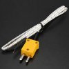
Thermocouple wire ($3)
Ardruino/Breadboard/miscellaneous ($5)
LCD 1602 ($3)

Parts Pictures:

05 thermocouple wire.jpg 02 31850 tc amp.jpg 03 4-channel level shifter.jpg

04 arctic alumina thermal adhesive.jpg
continued below....
 

_MrBelvedere_

Well-Known Member
Assembly:

Get the thermocoupler amp board and solder the headers to it.

IMG_6496 (Medium).JPG

IMG_6487.JPG
IMG_6491.JPG

Do the same with the leveler board:

IMG_6490.JPG

Add these two boards to the breadboard and add jumpers. Make sure it looks like a rats nest like this:


IMG_0017 (Medium).JPG

Unscrew the yellow plug off of thermocouple wire. Then mix the 2-part thermal adhesive:

IMG_0016 (Medium).JPG


Glue the thermocouple sensor end of wire to the COB at the tiny tc junction point.

IMG_6499 (Medium).JPG
Screw the other loose end of thermocouple wire into the MAX31855 blue terminal blocks on the board.

continued below....
 

_MrBelvedere_

Well-Known Member
Now the Ardruino code has been rewritten to take the temperature from the DS18B20 digital sensor and also the MAX31855 simultaneously so we can see if there are any big differences in their readings.... or we will see if one is faster to respond to temperature increases.

The LCD will now readout something like this:

TC: 65.69 D: 70:30 (Fahrenheit temperatures)

Code:
#include <OneWire.h>
#include <DallasTemperature.h>
#include <LiquidCrystal.h>
// Data wire is plugged into pin 6 on the Arduino
#define ONE_WIRE_BUS 6
// Setup a oneWire instance to communicate with any OneWire devices
// (not just Maxim/Dallas temperature ICs)
OneWire oneWire(ONE_WIRE_BUS);
// Pass our oneWire reference to Dallas Temperature.
DallasTemperature sensors(&oneWire);
//variables
int numberOfDevices;                          // Number of temperature devices found
DeviceAddress tempDeviceAddress;             // We'll use this variable to store a found device address
int TEMPERATURE_PRECISION = 12;
unsigned long time0 = millis();
//lcd setup
LiquidCrystal lcd(12, 11, 10, 5, 4, 3, 2);
int backLight = 13;    // pin 13 will control the backlight
String strI;
float tempCelsius;
float tempFahrenheit;
String strC;
String strF;
String strThermocoupleF;
float ThermocoupleF;
String strDigitalF;
float DigitalF;

void setup(void)
{
  // start serial port for viewing temps on laptop
  Serial.begin(9600);
  Serial.println("-= COB Multiple Temperature Sensor Readings=-");
  sensors.begin();  // Start up the library

  // Grab a count of devices on the wire
  int numberOfDevices = sensors.getDeviceCount();

  // locate devices on the bus
  Serial.print("Locating devices...");

  Serial.print("Found ");
  Serial.print(numberOfDevices, DEC);
  Serial.println(" devices.");

  // report parasite power requirements
  Serial.print("Parasite power is: ");
  if (sensors.isParasitePowerMode()) Serial.println("ON");
  else Serial.println("OFF");

  // Loop through each device, print out address
  for (int i = 0; i < numberOfDevices; i++)
  {
    // Search the wire for address
    if (sensors.getAddress(tempDeviceAddress, i))
    {
      Serial.print("Found device ");
      Serial.print(i, DEC);
      Serial.print(" with address: ");
      printAddress(tempDeviceAddress);
      Serial.println();

      Serial.print("Setting resolution to ");
      Serial.println(TEMPERATURE_PRECISION, DEC);
      delay(100);
      // set the resolution to 9 bit (Each Dallas/Maxim device is capable of several different resolutions)
      sensors.setResolution(tempDeviceAddress, TEMPERATURE_PRECISION);

      Serial.print("Resolution actually set to: ");
      Serial.print(sensors.getResolution(tempDeviceAddress), DEC);
      Serial.println();
    } else {
      Serial.print("Found ghost device at ");
      Serial.print(i, DEC);
      Serial.print(" but could not detect address. Check power and cabling");
    }
  }

  //LCD setup
  pinMode(backLight, OUTPUT);          //set pin 13 as output
  analogWrite(backLight, 150);        //controls the backlight intensity 0-254

  lcd.begin(16, 2);                   // columns, rows. size of display
  lcd.clear();                        // clear the screen
  lcd.setCursor(0, 0);                // set cursor to column 0, row 0 (first row)
  lcd.print("Hello. Starting Up... ");       // input your text here
  lcd.setCursor(0, 1);                // move cursor down one
  delay(3000);
}

void loop(void)
{

  Serial.print("\nTime: ");
  print_time(millis() - time0);

  numberOfDevices = sensors.getDeviceCount();
  String strNumberOfDevices = String(numberOfDevices);
  // call sensors.requestTemperatures() to issue a global temperature request to *all* devices on the bus
  sensors.requestTemperatures(); // Send the command to get temperatures

  for (int i = 0; i < numberOfDevices; i++) {
    strI = String(i + 1);
    tempCelsius = sensors.getTempCByIndex(i);
    tempFahrenheit = Celcius2Fahrenheit(tempCelsius);
    strC = String(tempCelsius);
    strF = String (tempFahrenheit);

    //print temps to computer
    Serial.print("\nTemperature Device #" + strI + ":  ");
    Serial.print( strC + " C / " + strF + " F "  );

    //address: 3BDC1F19000000A3 is thermocouple sensor which is device #2
    //address: 2816E9DE0600001B is the digital  sensor which is device #4


    //prepare temps for lcd
    if (strI == "2") {
      strDigitalF = strF;
    }
    else if (strI == "4") {
      strThermocoupleF = strF;
    }

    //print temps to lcd
    lcd.clear();
    lcd.print("TC:" + strThermocoupleF + " D:" + strDigitalF   );
  }

  delay(1000);
}


// function to print a device address
void printAddress(DeviceAddress deviceAddress)
{
  for (uint8_t i = 0; i < 8; i++)
  {
    if (deviceAddress[i] < 16) Serial.print("0");
    Serial.print(deviceAddress[i], HEX);
  }
}

void print_time(unsigned long t_milli)
{
  char buffer[20];
  int days, hours, mins, secs;
  int fractime;
  unsigned long inttime;

  inttime  = t_milli / 1000;
  fractime = t_milli % 1000;
  // inttime is the total number of number of seconds
  // fractimeis the number of thousandths of a second

  // number of days is total number of seconds divided by 24 divided by 3600
  days     = inttime / (24 * 3600);
  inttime  = inttime % (24 * 3600);

  // Now, inttime is the remainder after subtracting the number of seconds
  // in the number of days
  hours    = inttime / 3600;
  inttime  = inttime % 3600;

  // Now, inttime is the remainder after subtracting the number of seconds
  // in the number of days and hours
  mins     = inttime / 60;
  inttime  = inttime % 60;

  // Now inttime is the number of seconds left after subtracting the number
  // in the number of days, hours and minutes. In other words, it is the
  // number of seconds.
  secs = inttime;

  // Don't bother to print days
  //sprintf(buffer, "%02d:%02d:%02d.%03d", hours, mins, secs, fractime);
  sprintf(buffer, "%02d:%02d:%02d", hours, mins, secs);

  //lcd.print(buffer);
  Serial.print(buffer);
}

float Celcius2Fahrenheit(float celsius)
{
  return celsius * 115 / 64 + 32; // max celsius is about 280    Note: 115/64 = 1.796875  ~~ 0.3% error in theory in practice it will round downwards so it will be worse
}
After running it, the temperatures are nearly the same. The thermocouple wire is about ten degrees cooler but that is no big deal.... both numbers are close enough. And no matter how fast the temperature rises they both keep pace just fine. They are both using the Dallas 1-Wire protocol so unlimited sensors can be used easily without crowding out the Arduino.

Here it is running and comparing the two sensor types:


After running for about an hour, the temperatures stayed steady at 147F. So will run an oscillating fan on the whole rail to see how much that helps. And keep test adding COBs closer together until there is near nuclear meltdown :)

finalTemp.JPG


After adding a simple wall fan blowing air around the lights, the temperature dropped 20 degrees in about two minutes:

withFan.JPG


Are we having fun yet?
 
Last edited:

heckler73

Well-Known Member
I just looked at the pics and got scared when I saw the numbers.
Then I realized it was Fahrenheit. :lol:

How much did the K-Type board cost? EDIT: NVM I see the price above now.
And how did you get it so fast? Do you have an Arduino store near you or what?


I also just noticed you have the K-TC junction with exposed wires at the board. That may be the cause of the discrepancy, since the board junction is "reference", IIRC, hence the "cooler" reading due to ambient losses. One way to test that is try breathing on the wires at the board (use a straw or something that will localize the air). If it shifts, then you might need to tighten up that connection or insulate them better.
If it doesn't, then my hypothesis is in err.

BTW fantastic experiment!
 
Last edited:

_MrBelvedere_

Well-Known Member
Paid extra to get the kboard from Adafruit fast.

OK cool I did not realize that about the exposed wires. Yes when I took off the yellow socket the insulation was really close to the screws that the thermocouple wires were wrapped around so that makes a lot of sense. Will mess around with it more and try to get a really tight connection with no exposed wires. Thx and hope to hear some updates on your pulse experiment!
 

salmonetin

Well-Known Member
...ese mr....:clap:...;)

...new tutorial for max31855 in sparkfun... more info inside..

https://learn.sparkfun.com/tutorials/max31855k-thermocouple-breakout-hookup-guide


...curious thermocouple connector... ;)


https://www.sparkfun.com/products/13612

PD...tutorial for various thermocouples...;)...using 1 wire way with thermocouples too...

https://learn.adafruit.com/adafruit-1-wire-thermocouple-amplifier-max31850k?view=all

...and my curious offtopic vid... ...i told you Wilson... ;) ...13 friday....:fire:


...links and vids are onlt for examples or ideas...

:peace:

Saludos
 
Last edited:

medicinehuman

Well-Known Member

satdom

Well-Known Member
Is there a object oriented way of including the code into your arduino? So that it could be used if you're Arduino is already used for irrigation And lights?
 

alesh

Well-Known Member
Is there a object oriented way of including the code into your arduino? So that it could be used if you're Arduino is already used for irrigation And lights?
Yeah Arduino has some object oriented features of c++.
 
Top