electrical question for fan

desert fox

Well-Known Member
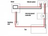
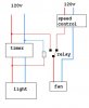
Will this set up work? I have a fan rigged up to a rotrary speed controler. I want to have the fan running full bore when the lights are running off the same timer. When the timer shuts off it will run on just off of the speed controler? Is this set up safe? I am not doing anything crazy just running a 400HPS and the fan off of the timer.
 

Attachments

Atomizer

Well-Known Member
The schematic appears to show a live mains connection running to both the speed controller input and output, it won`t like that too much if its triac based. It may be better to use the timer to control a 120v coil spdt or dpdt (changeover) relay which will route power directly to the fan when the lights/timer are on and via the speed controller when the lights/timer is off. The timer is off in the attached diagram.
 

Attachments

desert fox

Well-Known Member
the changeover relay sounds expensive, and I am trying to keep the wiring as simple as possible.

In my picture the hot lead is basicly split with the common running right to the fan. When the timer is on it will take the path of least resistant (through the timer) running at full bore. When the timer is off it then cuts off the main hot lead and therefore the only way to connect the circuit is through (auxiliary) the speed control.

I guess my main concern is if it is safe to have a hot lead going through a timer without having the common go back through the timer itself?
 

Atomizer

Well-Known Member
It`ll be fine when the timer is off as the live will be open circuit at the timer.
When the timer is on, you have the live from the 120v outlet on the speed controllers input which is ok.. but also in parallel on the controller outlet via the timer. Effectively both the inlet and output of the controller will be connected to the mains live wire :wink:
A mains coil relay wont cost much and doesn`t need to be overly beefy as its only running the fan.
 
Top