Microcontrolled LED Grow Cabinet

GonnaRobYa00

New Member
Hi everyone,

I am new to the forum, although I have browsed and extracted a lot of information from many posts. I have decided I would like to give back to the community by documenting the design and construction on a small cabinet-style grow room. I have a good supply of knowledge from working as an electrician and now studying electrical engineering.

I am currently in the process of designing a grow-cabinet. I would like to include in this thread the detailed design including schematics, block diagrams, 3D models etc.. to help anyone who would like to build one themselves. Input is greatly desired and appreciated, as I am not an expert. I have personally finished 1 indoor closet grow and 1 outdoor grow, both with great results.

The second post in this threat will serve as an update log, where I will post new drawings and photos, etc.

For the grow-cabinet, I have created a list design considerations which should give a good background to the project.

Design Considerations
1. Size
- Overall Depth x Width x Height = 28" x 52" x 60"
- Depth chosen to fit doorway​
2. Features
- Microcontroller (ie. computer controller)​
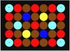
- LED Lighting equivalent to 400Watt HID lamp, DIY style
- Good airflow, ventilation, uniform temperature
- Carbon filter for smell
- Hydroponics/Aeroponics
- Humidity Control, raise/lower
- Temperature Control, heat/cool
- Fan speed Control, faster/slower​
3. Construction Materials
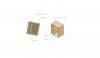
- Medium Density Fibreboard (MDF), Structure
- Circular sheet metal ducting, HVAC
- Glossy white or other reflective paint, Structure walls
- Various electronic components (transistors, resistors, IC's, CPU, PCB's, etc)
- Plexiglass, custom size reservoir
- Pumps (air/water), hydroponics
- PVC Tubing, hydroponics
- Various fasteners (glue, screws, nails, etc)
- Probably a lot of others​
4. Cost
- As cheap as possible without sacrificing performance​
5. Timeline
- It could be a long process

If you would like to post your own ideas, please do!
 

GonnaRobYa00

New Member
Updates

October 21, 2013
Thread created. Quick project background given, preliminary cabinet model and LED system diagram uploaded

October 23, 2013
Added more details regarding LED light source, uploaded preliminary schematic
 

GonnaRobYa00

New Member
Here is a quick look at the over layout of the cabinet, as well as my idea for the LED lighting control. I will add more detailed drawings as soon as I can!

LED System
I plan on controlling N 7-led lighting panels using the BCD to 7-segment display driver, where the 7-segment display will be replaced by an LED panel containing 7 leds. I am still researching specific wavelengths(nm) as well as different ratios to use. The parallel ports, A and B, are part of the microcontroller. By inputting a 4-bit binary value using the selector switch (15 different settings available), I want to generate a corresponding output which will decide which LED's (on each panel) will be turned on and at what brightness. The led panel output relays the output of the BCD-7seg driver to the next led panel.
led block diagram.jpg


Overall Structure
This should give a good idea of what I want the outside to look like, this drawing has dimensions (DxWxH) of 38" x 52" x 60", so it is incorrect, but it still shows the overall idea. The holes are just some I threw in there for duct work.
main structure.jpg
 

astroastro

Active Member
Gonna- I think you are going to need at least 100W of LED power, and probably more, like maybe 150 - 200W for this space. At these levels of light power, you are going to consume a lot of power using a constant voltage power supply as you have shown, vs a constant current power supply. I would highly suggest you use separate power supplies for the LED's which have been designed for use with high power LED lighting. You are going to consume a lot of power for those LED's one way or another- using a voltage clamped constant current LED driver will reduce your currents and compensate for varying Vf (forward voltage) of the LED's.
 

GroErr

Well-Known Member
Looking good :) On the lighting, I have a 405W LED panel in a 24"Wx48"Lx63"H cabinet and it's just about right, definitely not overkill and I may add another small panel to supplement lighting during flowering, you should consider 400-500W LED for this space (assuming if the overall width of flowering area is approx. 36" from your drawing), 150-200W could be Ok for vegging but I'd say under-sized for flowering. Most panels regardless of manufacturer should provide a sq. ft. coverage area, my 405W panel claims to cover 12 sq. ft. 2 cents....
 

GonnaRobYa00

New Member
Thanks for your inputs. I wanted to make each LED panel somewhat small, say 50-100W. I've been playing around with Micro-CAP (electronics software) and this is what i've come up with. The voltage supplies, b0-b7 would represent the I/O pins from a controller. Potentiometers are used to control brightness, not really necessary though. LED switching is controlled with the MOSFET's and controller I/O pins. LED wavelengths are as follow: Blue 440-460nm, Red 620-670nm, white 2700K, 3000K, 3500K, 4000K (2x 3500K and 4000K). I added the white leds to broaden the spectrum a bit. The forward voltages, max currents, lumen outputs etc are based on Phillips LUXEON Z color LED datasheets and PHillips LEXEON Z white LED datasheets.
Color - http://www.mouser.com/catalog/specsheets/Lumileds-LXZ1.pdf
White - http://ca.mouser.com/ProductDetail/Philips-Lumileds/LXZ2-3580-3/?qs=sGAEpiMZZMu4Prknbu83yxCHVnPUEm96aKBk9n9i2tg=
LED schematic.jpgsorry, this should be rotated.


I've been doing a lot of research regarding wavelengths of light required by plans for photosynthesis, wavelengths of HPS/MH bulbs, etc. Correct me if I'm wrong but this is what I'm thinking.

Peak wavelengths for photosynthesis around 450nm and 670nm, with 620nm required for 2.5hours per day(flowering)

A typical HPS lamp emits light according to the spectrograph below. 400W Eye Hortilux HPS has 55000 initial lumens. HPS produces a lot of heat, so the bulb will have to be places farther away from the plants. Luminous flux is proportional to the square of the distance from source. By targeting the specific range of wavelengths required by the plant, you will produce more usable light at the same power(Watts LED vs. Watts HPS), so an LED light source array will require less power to produce the same amount of usable light that an HPS lamp would do.
View attachment 2868500
 

astroastro

Active Member
Gonna- with a few extra parts your schematic would technically work, but it is a very inefficient design in terms power efficiency and part utilization. Just an opinion- what you need to do is get a dedicated voltage clamped, constant current LED driver. This is the correct way to drive series strings of power LED dies. Driving different types of LED's, like AlInGaP reds and InGaP blues, with a common LED driver can be problematic. Try to use only one type of (color) LED in any one series string, and make every attempt to match the cumulative Vf of the series strings to each other. Driving different types of LED's, like AlInGaP reds and InGaP blues, with a common LED driver can be problematic.

A constant current LED driver with a clamp voltage of about 40V will allow you to use maybe 10 blue on a single series string, and a few more red LED's . The operating voltage of the driver will drop to the highest series string Vf and stay there, while current will be modulate by the driver- no resistors, no power lost in the resistors.

Put a gate resistor on one of those transistors and drive a 12V relay to turn the LED driver AC ON and OFF. Use a 4001 reverse biased diode across the relay coil for flyback.
 

GonnaRobYa00

New Member
Thanks for the advice astro. I didn't even think of the massive power loss in those resistors bongsmilie
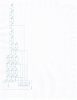
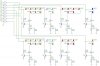
. I've redone the led schematic, and theoretically this is about 80% (83.24%) efficient, assuming each LED is putting out 3W. V1-V8 are used to power each section of LEDs. I've divided them up because I would like to be able to have some control over how many leds are on (not really necessary, but It would be cool to see how using different amounts of light at different wavelengths/colour temp would effect growth). The small resistor divider connected to the drain/base of the mosfet/bjt is there to serve as a current trimmer. The potentiometer is 10ohm, and can be used to adjust the current in each string of leds from about 600mA to 1200mA. I added it because no non-linear device behaves exactly as it should, and I want to be able to tweak the current to exactly 1000mA for each string.
LED_schematic_revised.jpg
I've been looking around at LED manufacturers some more, and the Cree XP-E2 series seem to be quite good.
Specs for the Leds in the schematic are:

LED ColourCurrent MaxVf typ @ ImaxOutput(lm or mW)
1-14Warm White ~6500K1000mA3.15V218-266lm
15-20Cool White ~2700K1000mA3.15V191-218lm
21-31Red - 620-630nm1000mA2.65V156-203lm
34-35Red-Orange - 610-620nm1000mA2.65V172-258lm
32-33Royal Blue - 450-460nm1000mA3.5V1035-1323mW

I've also created an picture that shows my idea for the layout of the leds in a panel. Each led would be housed in a reflector/lens. The colours are as follow:
ColourWavelength/CT
BrownWarm White ~6500K
Light BlueCool White ~2700K
RedRed 620-630nm
YellowRed-Orange 610-620nm
BlueRoyal Blue 450-460nm

led_layoutv1.jpg
Any suggestions on improving this layout would be very helpful! Dimensions are 14"x10.2".
 

astroastro

Active Member
Gonna- not sure if what you have there is going to run at 80% efficiency as you expect. The source current of the FET is going to be carrying all the overhead volatage from the LED strings (supply voltage of 14 or 26V - string Vf x FET source current). You are going to be running this power thru the FET and the resistor chain between the FET source pin and ground. This is all wasted power, and those parts are going to get hot, I am not sure they will survive. In addition to this the LED's are going to get smoking hot at 1000mA forward current unless you have a really good thermal plan.

If do not want to get an off-the-shelf constant current LED driver, which is what I suggest you do, perhaps you could try incorporating a part like a TI TL4242 or an On Semi NSI50150AD- I have never used these parts before in a design and have done little beyond a simple Google search to find them, but it may be something worth looking into. I would really, seriously advise against attempting to drive LED's at these power levels with a constant 14 or 26V supply as you have shown. [h=1][/h]
 
Top