You are using an out of date browser. It may not display this or other websites correctly.
You should upgrade or use an alternative browser.
You should upgrade or use an alternative browser.
My LED Experiment
- Thread starter budsbunny
- Start date
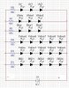
Here is the schematic drawing for how I wired the LEDs as asked. Its not rocket science and anyone who has some electrons background already knows this. I am posting this so that maybe I can inspire someone to get into this.
As you see the groups of different color LEDs, I just grouped them together. So lets say you look at the red group of 5 LEDs, well if you wanted to add another 5, you connect them the same way as above. You can use as much LEDs as your power supply can handle.
For now, I got some cheap AC to DC converters off ebay. If you go here: https://www.rollitup.org/do-yourself/208286-diy-cheap-led-array.html This is where I made my LED array version 1. I am doing my version two. As for the converters (power supply), I had modified them. They were origionally made for car adaptors, but I dismantaled it and added some wires.
As for a power supply, theres a cheap way to make one. If you have an old power supply (PSU) from an old computer, you can modify it to power your LEDs. I found this site very helpful:
http://www.magicratproductions.com/magicforum/viewtopic.php?f=5&t=131
I will be making one myself to power my LEDs. The benifit with these power supplies is that it will have high current capacity.
My current power supplys are 1A. There is two of them. If your LEDs are suposed to draw about 20 mA of current, idealy you will need about 50 groups of LEDs (those 5 red LEDs after the resistor is what I call a group.)
With a cheap power supply, depending on the specs, you can run anywhere from 600 to over 1000 led groups. If its all red, thats about 3000 - 5000 LEDs.
I also used a 12v DC power supply. You can use a 24, and have 10 leds in one group instead of 5 with one resistor.
Something to keep in mind is this formula: Voltage(V) = Current (I) x Resistance (R)
Lets say I have a red LED. It drops about 1.8v to 2.2v (check your specs sheet). This means that if I have 1 LED and 1 Resistor, My LED will have about 2.2v across it, and the resistor will have 9.8v across it.
With that being said, we know the voltage across the resistor, and we know what is the optimal current for the LED (20 mA ... the little m means that it is 0.02 A, if you are not familiar with engineering notation)
Now we can find out what resistor we can use. 9.8v = (0.02)R
R = 490 ohms. So we look for a 490 ohm resistor.
Now we look for a resistor with that value. Radio shack and Ebay sell these. The resistors will have color bands on them to indicate their value. Here is a website to decode the color bands:
http://www.dannyg.com/examples/res2/resistor.htm
When buying resistors for the project, I used 1/4 watt resistors.
With that being said, we can optimize to have the maximum number of LEDs in series (in a row connected positive to negative leads). We know that the red ones drop about 1.8 to 2.2v. If we use 6, the maximum that our LEDs will drop is 13.2v. Our power supply cant handle that. If we connect 6 or more LEDs, they wont turn on. It will be like an open circuit.
If we use 5, we will be dropping 11v. This will leave 1v across our resistor. With the formula above, you can calculate which resistor you need.
V = 1V
I = 20mA or 0.02A
R = ?
If you look at my DIY array thread, you will see in real how I wired them. Soldering is key, and with my Version 2 array, I hot glued the LEDs together.
It is pretty simple and anyone can do it. LEDs are cheap. My plant is only a few weaks old but it looks like it has more then enough light.
The heat produced by the LEDs is about 40c. When I touch it, its no warmer then my body. They are on all day and that is all the heat that they produce.
I will connect a wattage measurement tool (kill-a-watt) thing to see how much wattage im drawing.
I will post the wiring for my PSU driver for my LEDs, and my completed LED array V2. Its going to be huge.
Also, theres an error in the picture that I just realized. The LEDs above the red should say amber.
Attachments
Also been following your thread man, I would love to see the LEDs get better and better. I saw this today and thought I would post it up for you (not sure
water cooled led
http://www.engadget.com/2009/07/15/eternaleds-debuts-worlds-first-liquid-cooled-led-light-bulb/
http://www.eternaleds.com/News-a/134.htm
http://www.earthled.com/evolux-led-light-bulb.html
Dunno what ur spec's are....
* Light Engine: CREE® XRE LED Light engine
* Power Consumption: 13 Watts Max (12 Watts Typical)
* Input Voltage: 90~277 V AC (Worldwide Capable)
* Luminous Flux: 1075 (Cool White), 1000 (Warm White)
* Color Temperature: 3000 K (Warm), 6000 K (Cool)
* CRI: 75 - Cool , 80 - Warm
* Beam Angle – 180 degrees overall
* Operating Temperature Range:
* -4°~113° F (-20°~45° C)
* Operating Humidity Range: 20%~90%
* Lifespan: > 50,000 Hours (MTBF)
* Construction: Flame Retardant Plastic
* Aluminum Heatsink, Shatterproof Lens
Thanks, thats really cool. I cant wait to replace my micky mouse LEDs with this nice looking bulb. It took me way too long to make 150 LED array. This would save a lot of time for me and will give the UFO system a run for its money. That thing is WAYYY too overpriced. My huge array is still in planning mode, but so far, about $60 for almost 1000 LEDs. That beats the $200-400 price tag.
I would love to use one of those and see what its like. Thanks again for posting that up. No worries about getting water on the lense and having it shatter like the other lighting systems. And no worries about temprature increases since it looks like it doesnt heat up past 40c.
Many advantages to this along with little to no energy fingerprint.
Speaking of LED lights, I found this on the net.
http://www.lck-led.com/p478/Extreme-Bright-100W-High-Power-Led---110¡C/product_info.html
its a 100w white light array capable of producing 4000-6000 lumens. They have warm light (2700-3300K) and white light (6000K to 7000K) for $100. For the price of those UFO systems, you can put 1 white, 1 red and 1 blue and produce 12 000 lumens of light that your plant uses. ORRR even better, screw the white, just red (620-635nm), yellow(580-595nm) and blue(460-470 nm).
Now im thinking of getting these for my future clones and see what happens.
I know this isnt a journal post, but for the ones who are interested in growing with LEDs, this is some good stuff.
stonedfisher
Member
Speaking of LED lights, I found this on the net.
http://www.lck-led.com/p478/Extreme-Bright-100W-High-Power-Led---110¡C/product_info.html
its a 100w white light array capable of producing 4000-6000 lumens. They have warm light (2700-3300K) and white light (6000K to 7000K) for $100. For the price of those UFO systems, you can put 1 white, 1 red and 1 blue and produce 12 000 lumens of light that your plant uses. ORRR even better, screw the white, just red (620-635nm), yellow(580-595nm) and blue(460-470 nm).
Now im thinking of getting these for my future clones and see what happens.
I know this isnt a journal post, but for the ones who are interested in growing with LEDs, this is some good stuff.
Nice find, and nice journal.
I have spent too much time today researching leds. It looks to me like that 100w panel also needs a low volt power supply. Am I thinking correctly that to operate the red array that you would need a 24vdc regulated 4amp power supply and for the blue array a 36vdc regulated 3amp power supply?
Even then for 600 bucks you could have a similar array to those 1400 dollar super grow led arrays.
It seems that from what I have read only the red and the blue are necessary for plant development.
I really want to get one of these panels and try it out supplementally.
You can modify a computer power supply and tap in to the 12 v. Step it up to 24v. Mind you if you connect it to +12v and -12v you can still get 24v but usually in these power supplies -12v can only handle like .6A like mine.
I'm not too sure but I think this one can run from 90vac to 240vac which is a good thing.
I'm not too sure but I think this one can run from 90vac to 240vac which is a good thing.
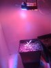
Day 29
A few more leaves sprouted. So far I have no problems with LEDs, just growth seems a bit slow, but what do I know, im a virgin.
Maybe another 1/2 month to a month and Ill get a better LED array.
Going to start nutes the next time I water. Got my TDS meter.
A few more leaves sprouted. So far I have no problems with LEDs, just growth seems a bit slow, but what do I know, im a virgin.
Maybe another 1/2 month to a month and Ill get a better LED array.
Going to start nutes the next time I water. Got my TDS meter.
Attachments


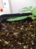
So, I have been reading a lot about deficiency in our plants and found something that caught my eye.
It said that calcium deficiency causes leaf tips to twist. I remembered seeing mine like that but just thought it was just my eyes playing tricks on me.
I turned on a white light on my plant to make sure and snapped some pictures. Now im asking the experts, is this a calcium deficiency or is this just genetics?
On to the update. I mixed a 400-406 ppm mixture of 24-8-6 miracle gro. I used tap water that I dechlorinated by leaving it to evaporate overnight. I didnt check the initial ppm, but I think she will be fine.
I connected a small submersible pump to a drip system that I made. The pump was free from a broken fountain, the 1/2 inch to 1/4 tubing adapter was about $4, the tubing was like $10 (but it was WAYYYYYY more then I need), and the drip tips (2gph) ran me about $3 for 4 of em. Then a timer for less then $10 (sale on a digital timer), and now its set to water every second day for 10 mins. Hopefully Im not overwatering.
I also made a CO2 "generator" (I dont know what to call it). I got some yiest, sugar and warm water. Poked a hole in the top of the 2L bottle, put in my 1/4inch tubing, sealed it, and on the other end of the tubing, I put another drip end.
I noticed that whenever I blow really hard through the drip end, no matter how hard, the air that came out was always at the same pressure. So its kind of a cheap pressure regulator. I shook up hte bottle and it became as hard as a rock. I heard the CO2 comming out of the other end.
So yeah here are some pix with the lights on, not good ones cuz my camera is messed up. It zooms quite a bit for no reason and takes blurry pictures. its old anyways.
Attachments

If anyone has ever wondered how to power their LEDs or computer fan to your stealth cabnet grow then heres your source.
Drill holes, make sure that you drill the right amount. I thought I had -5v in my power supply. Turns out I didnt. Didnt look at what I had. Get some Binding Posts and screw them in. You have to make sure that they are properly insulated and not touching the metal. A good way to check if they are insulated is by taking your multimeter and turning it to this setting: -|>+ If you get a reading such as OL (overload), then it is insulated. If the numbers move, then there is some conductivity between the binding posts and your PSU. THIS IS BAD. I put electrical tape around my binding post's threads to insulate it.

So I started with a cheap power supply that i got for about $25. First thing is I unscrewed the four screws holding it together. MAKE SURE YOU ARE NOT PLUGGED IN!! even though your power supply is off, the connection from your 120v/240v to the circuit board is live! In this Power Supply Unit (PSU), I had an extra fan that I know I wont need. I wont be using this supply to the max so I dont need the extra cooling.

Now cut all the wires. The wires connected to the large connector (picture below: the right "loom") is the one that you will be using. Cut this one about 6-7 inches from the circuit board. The ones on the left side of the picture, you can cut those short, they will not be used.

Notice how my wires that are not using are so short? And the ones that I will be using are longer? well that is what it should look like when you organize you wires.

Green goes to ground (the black wires), Brown goes with the oranges. Gray and purple you can put together. I soldered them together and used electrical tape to insulate them. You should do the same.

Now solder the wires to your binding posts.
+12v is yellow
+5v is red
+3.3v is orange (+brown)
0v (ground) is black (+green wire)
-5v should be white
-12v is blue

Now screw it back together and you are done!! If you connect a fan to 0v and 3.3v, it is VERY slow. between -12v and +12v, it is very fast (24v).
This is what I use to power my LEDs and computer fans.
If the fan on your PSU (the built in one) does not turn on, then there is something wrong.
Troubleshooting:
If it doesnt turn on, check the fuse in the PSU. If it is blown, you have not properly insulated something and its shorting.
Check your purple and gray connections if the fan does not turn on.
Remember green goes to black.
and brown goes to orange.
If you got any questions, feel free to ask.
Drill holes, make sure that you drill the right amount. I thought I had -5v in my power supply. Turns out I didnt. Didnt look at what I had. Get some Binding Posts and screw them in. You have to make sure that they are properly insulated and not touching the metal. A good way to check if they are insulated is by taking your multimeter and turning it to this setting: -|>+ If you get a reading such as OL (overload), then it is insulated. If the numbers move, then there is some conductivity between the binding posts and your PSU. THIS IS BAD. I put electrical tape around my binding post's threads to insulate it.
So I started with a cheap power supply that i got for about $25. First thing is I unscrewed the four screws holding it together. MAKE SURE YOU ARE NOT PLUGGED IN!! even though your power supply is off, the connection from your 120v/240v to the circuit board is live! In this Power Supply Unit (PSU), I had an extra fan that I know I wont need. I wont be using this supply to the max so I dont need the extra cooling.
Now cut all the wires. The wires connected to the large connector (picture below: the right "loom") is the one that you will be using. Cut this one about 6-7 inches from the circuit board. The ones on the left side of the picture, you can cut those short, they will not be used.
Notice how my wires that are not using are so short? And the ones that I will be using are longer? well that is what it should look like when you organize you wires.
Green goes to ground (the black wires), Brown goes with the oranges. Gray and purple you can put together. I soldered them together and used electrical tape to insulate them. You should do the same.
Now solder the wires to your binding posts.
+12v is yellow
+5v is red
+3.3v is orange (+brown)
0v (ground) is black (+green wire)
-5v should be white
-12v is blue
Now screw it back together and you are done!! If you connect a fan to 0v and 3.3v, it is VERY slow. between -12v and +12v, it is very fast (24v).
This is what I use to power my LEDs and computer fans.
If the fan on your PSU (the built in one) does not turn on, then there is something wrong.
Troubleshooting:
If it doesnt turn on, check the fuse in the PSU. If it is blown, you have not properly insulated something and its shorting.
Check your purple and gray connections if the fan does not turn on.
Remember green goes to black.
and brown goes to orange.
If you got any questions, feel free to ask.
born2killspam
Well-Known Member
Why not just isolate & rectify the mains?? LEDs don't need regulation..
If your saying build a full wave rectifier, then yeah thats a possibility, but 90-220v dc is bloody dangerous. Building the circuit, soldering... its easier to do it this way (took me less then an hour). Plus anyone with a background in electronics that knows how to build this circuit will definitely have an old computer power supply lying around = free parts. I had one, but it was still in use. If you ask someone at a computer repair shop, they will probably have a old power supply that works, and they are probably willing to part with it. If they are stingy, then they will part with it for a price. They were asking for $20 for me, I laughed and went to the computer store next door.
born2killspam
Well-Known Member
I don't solder directly connected to mains unless its absolutely necessary myself.. And the need has never come up..
ohhh thats what you mean, soldering the binding posts right? I dont know where my mind is, my bad. These binding posts didnt come with any way to attach the wire to it. It came with some small plate with two holes, I soldered it to that. I find it easier to solder, place the wire to it, heat and touch with solder. easy as pie. Solid connection. Its not like im going to take it off some time in the future.
But then again, everyone has their own oppinions. thats why no electrician solders anymore. It was left behind with the knob and tubing.
But then again, everyone has their own oppinions. thats why no electrician solders anymore. It was left behind with the knob and tubing.
born2killspam
Well-Known Member
Not as solid a connection as you may think.. I highly advise you to learn proper soldering technique.. In the mean time, alot of flux will really help your connections.. Proper technique is good, and flux is good..
Day 35

Temp: Night: 75 F, Day 82 F
Light: 18/6
Water: 406 ppm, 6.1 pH, 24-8-6 Miracle Gro
Watering Schedule: 2/week for 10 mins, 2GPH head.
Plant Height: 2.5 in
Plant Width: 4.5 in
Stem Width: 1/8 in
I noticed that I had a bit of white mold on the surface of my soil. Googled it and found out that it is a mold not harmful to my plant. My problem was that I had fresh air comming in, but not air circulation + too frequent watering cycle.
The surface needs to dry out and I wasnt letting that. Its because the LEDs produce little heat. Not enough for the surface to dry. Air circulation will help that and changing it to water twice a week is better.
Note for future or current LED growers, keep your soil ventilated even though you just have a seedling. I think this might even be true for CFL users.
digitalliquid
Active Member
awesome thread i was reading alot about leds and just going to throw in some of the knowledge i gathered. biggest thing i want to ask is how much heat is your panel giving off? and if its not alot why dont you have it closer to your plant? remember LEDS loose much of there lumens every X amount of inches away (and its drastic). second is i have found that the more expensive leds tend to have a higher lumens output and better light intensity in my opinion it would be better to go with that (maby ill try it out). nice job man your making my ideas and thoughts into a tangibal reality! i want to try this project at some point in the future but i dont quite understand how current and resistors work , however i found a shop on ebay with high output leds and each one has a small resistor built in. they were like 40$ for 50
Similar threads
- Replies
- 38
- Views
- 3K
- Replies
- 35
- Views
- 4K
- Replies
- 1
- Views
- 400