Tube PA conversion

Dreaming1

Well-Known Member
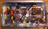
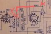
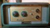
I have a 1954 Rauland-Borg model1916 PA head. Schematic in hand. Looks like an old 50s Gibson octal circuit. The outputs have continuity. I took the tubes out. 5Y3GT rectifier. I will put it back and check voltages at sockets and replace resistors before I put the others back. Then check these caps for AC leaking by. Wax paper from the 50s. Still spec? As long as the bias isn't off too bad, Im going to let it rip. 1 phono channel that is a 6SQ7 going to phase inverter. 2 channels (already tied parallel...) of 6SJ7 going to a 6SC7 mixer. 6SC7 paraphrase circuit phase inverter feeding 2 6V6GT power tubes. Cathode biased, negative feedback loop, 4,8,16Ω impedances.
Looks fun. Maybe it will sound old. I wish I had a field coil speaker. Looks like it will be dark sounding. May lower the cap values on inputs.
I just got the 3 wire cord in. Solder it up tomorrow and start drilling holes for jacks.
I am going to add a coupling cap and input resistor to the phono ch. I will play it if it works. Then im liable to try cascading the 6sj7 for a channel and cascade the 6SQ7 and 6SC7 as 2nd channel. Maybe triodes driving pentodes on 2 channels. Maybe try other octals.
Anyone been here before me? Hip to this trip? Come aboard and watch me lose a finger or find fun in electronics!
rauland_(1).jpg
20220329_011122.jpg
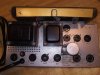
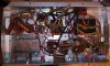
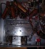
The guts. Grab and go action wiring.
20220329_004303_(1).jpg
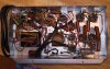
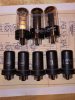
Bottles and cans, bottles and cans, well just clap your hands -Beck
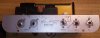
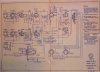
20220329_011903.jpg
The cypher key
20220329_011951_(1).jpg
 

Dreaming1

Well-Known Member
20220426_231933_(1)_(1).jpg
I decided to rip out the bakelite jacks. Fuck 'em. Going to be a working preamp playground, not a museum item. I plated the panel from behind. I will drill these for 1/4" jacks and a switch for 4/8/16Ω speaker impedance. May add one for selectable off/light/heavy negative feedback loop.
I have all of the electrolytic caps except the first filter cap. I have all of the resistors and the other caps.
Decided to run a bolt through a hole to use as chassis ground point instead of using the rectifier tube lead. Safety stuff.
I may remove the can cap and both the input socket things. Plate them off and use that area to mount a board holding the power filter stuff. Right by the input jacks though... Better than a pile of these bigger caps though.
Got a light bulb current limiter set up. Get some shrink wrap tubing and some of the jacks I want to use and I should be into rewire and testing the circuit. Then I will plug all the tubes back in and see if they all work. Then I may get to play it.
 

weedstoner420

Well-Known Member
Greetings fellow tube amp nerd, that's a nice find! Looks to be in good shape inside too. So many possibilities!
 

Dreaming1

Well-Known Member
Greetings fellow tube amp nerd, that's a nice find! Looks to be in good shape inside too. So many possibilities!
hey! You deep into this stuff? I have some questions about cascading preamp stages. I know impedance matching becomes a thing. Found rob robinettes page and uncle Doug on youtube for tech advice. Have a decent grasp of ohms law and the math to figure out bias and resistor values type stuff. But not a lot of experience. I bet redesigning these pre stages is going to be good experience and hopefully a good time that sounds good.
 

weedstoner420

Well-Known Member
I mean I know a bit... As far as impedance matching when cascading gain stages, just make sure the resistance after the coupling cap (including volume pot and/or grid leak resistor of the next stage) is much higher than the preceding stage's output impedance. Usually between 500k and a couple meg is fine. Not sure how much it actually matters but that seems to be how most amps are designed...

Also if you're cascading multiple gain stages, you may have to attenuate the signal pretty heavily between stages so it doesn't turn into a square wave too fast. That can be done with just a voltage divider - 2 resistors equivalent to a volume pot turned down very low.

When in doubt, start from a known good circuit/schematic and adjust component values to taste. All those octal tubes probably have 9-pin equivalents that may be used in other circuits you can use for reference (i.e. 6SJ7 is close to a 5879).

I hadn't heard of Rob Robinette but his page looks pretty cool! Unfortunately I don't have the attention span for long YouTube videos like uncle Doug... My main reference for stuff is Merlin Blencowe's books and articles (aka the Valve Wizard), so check him out too if you haven't already.

I'm following along and look forward to seeing where this thing goes!
 
Last edited:

Dreaming1

Well-Known Member
Thanks. I have looked through several preamp schematics for these 6.3v tubes. And checking the tube reference material. Looking at the curves. I will do some math, but also plan on using resistor/capacitor substitution boxes to change the circuit while I monitor the pins for current and voltage. And use my ears too.
I have the basic working knowledge of circuit design, but no insight or experience directly with amps. This will all be fun and or a learning curve fight.
 

weedstoner420

Well-Known Member
Thanks. I have looked through several preamp schematics for these 6.3v tubes. And checking the tube reference material. Looking at the curves. I will do some math, but also plan on using resistor/capacitor substitution boxes to change the circuit while I monitor the pins for current and voltage. And use my ears too.
I have the basic working knowledge of circuit design, but no insight or experience directly with amps. This will all be fun and or a learning curve fight.
Nice, I hope it's a fun learning experience! Like I said, a known amp schematic from like Marshall/Fender/etc is probably a good starting point, at least as far as the overall design, and tweak component values from there.

Looking at the schematic, I'd be tempted to just hook a guitar up to one of the mic inputs and see how it sounds. It's probably decently rockin' as-is (once you confirm it's electrically safe and operational of course).
 

Dreaming1

Well-Known Member
Im still at it. Had to focus energy in other areas of life.
20220601_152143_(1).jpg20220601_152256_(1).jpg20220601_152351_(1).jpg
so here is where and how Im building the filter cap section.
Maybe
I should lay some non-conductive sheeting over it before I layer the input section over it. The ground side will be by the input jacks. Im shrink wrapping all the wire connections too.
Switches will be for 4,8,16 Ω speaker impedance and the NFB will be switchable ( on 8 Ω right now) between off and 2 resistor values for more or less NFB.
I am just recapping it first. Then get it running with tubes and I will play it as is for a bit. Switch between .022 and .047 coupling caps at input to see which I prefer.
Going to make ch 2 be the phono tube and use 1meg resistor (on hand) and .047 cap for input on 6sq7. The schematic has 10meg and I have seen fender using 5meg. Should I use higher resistor value?
After I get it going and check it out, I will start with pairing the 6sj7 tubes in parallel as ch 1.
 
Last edited:

weedstoner420

Well-Known Member
Im still at it. Had to focus energy in other areas of life.
View attachment 5142749View attachment 5142750View attachment 5142751
so here is where and how Im building the filter cap section.
Maybe
I should lay some non-conductive sheeting over it before I layer the input section over it. The ground side will be by the input jacks. Im shrink wrapping all the wire connections too.
Switches will be for 4,8,16 Ω speaker impedance and the NFB will be switchable ( on 8 Ω right now) between off and 2 resistor values for more or less NFB.
I am just recapping it first. Then get it running with tubes and I will play it as is for a bit. Switch between .022 and .047 coupling caps at input to see which I prefer.
Going to make ch 2 be the phono tube and use 1meg resistor (on hand) and .047 cap for input on 6sq7. The schematic has 10meg and I have seen fender using 5meg. Should I use higher resistor value?
After I get it going and check it out, I will start with pairing the 6sj7 tubes in parallel as ch 1.
Those 6SJ7's are using grid-leak bias, which is more common for small-signal inputs like a microphone, not so much for guitar (maybe older guitars with low output pickups). The cathode is connected right to ground, and you need that super high value resistor (5-10 meg) to generate bias voltage on the grid. If you use the usual 1 meg in that spot, I don't think it would hurt anything, but it would be biased very warm and probably have very little headroom.

I think a more "contemporary" design would be a 1 meg grid leak resistor, and a resistor in the 1k - 2.2k range from the cathode (pin 5) to ground. The 6SQ7 for the phono input is already set up that way - the 0.5 meg pot acts as the grid leak resistor, and the 470 ohm above it (in the schematic) is the cathode resistor (shared with the 6SC7).
 
Last edited:

Dreaming1

Well-Known Member
Those 6SJ7's are using grid-leak bias, which is more common for small-signal inputs like a microphone, not so much for guitar (maybe older guitars with low output pickups). The cathode is connected right to ground, and you need that super high value resistor (5-10 meg) to generate bias voltage on the grid. If you use the usual 1 meg in that spot, I don't think it would hurt anything, but it would be biased very warm and probably have very little headroom.

I think a more "contemporary" design would be a 1 meg grid leak resistor, and a resistor in the 1k - 2.2k range from the cathode (pin 5) to ground. The 6SQ7 for the phono input is already set up that way - the 0.5 meg pot acts as the grid leak resistor, and the 470 ohm above it is the cathode resistor (shared with the 6SC7).
I meant what you said about more modern input, not just replacing the 10meg with 1meg. Maybe leave one and alter the other one for now. I just got the filter cap section done. Added another terminal strip to hold unused output transformer leads. If the tubes work, I might get to try it out over the weekend.
 

weedstoner420

Well-Known Member
I meant what you said about more modern input, not just replacing the 10meg with 1meg. Maybe leave one and alter the other one for now. I just got the filter cap section done. Added another terminal strip to hold unused output transformer leads. If the tubes work, I might get to try it out over the weekend.
Nice! (Edit: dang it, devil horns emoji doesn't translate from my phone...rock on!)
 

Dreaming1

Well-Known Member
20220604_233529_(1).jpg
I think I'm wired for sound. .047 cap on 1st ch and .022 cap on 2nd ch. I threw a .022 coupling capacitor before the .5meg pot. Is that right? I like the idea of a capacitor between my guitar and any DC volts. Just parked the other speaker outs and wired the 8Ω with the NFB to the output jack. I have to check my speaker collection. I think all my 12" ones are 16Ω, but I have a 4x12 cab that only has a pair in it. I can wire it for 8 or 16.
The old solder...what is up with that? Tough. And everything smells so different from modern toxic fumes. Extra lead? Maybe I can skip my paint chips today.
I will start with rectifier tube in and check some voltages. Then pop the rest of the tubes in and give it a go.
Need to grab some of those tube sockets with the leads on them and an analog ammeter. Then I can mess with bias on the power tubes if needed.
Maybe tomorrow, but probably mon or tues. If it works, I will record some and throw it up on yutube.
 

weedstoner420

Well-Known Member
View attachment 5144558
I think I'm wired for sound. .047 cap on 1st ch and .022 cap on 2nd ch. I threw a .022 coupling capacitor before the .5meg pot. Is that right? I like the idea of a capacitor between my guitar and any DC volts. Just parked the other speaker outs and wired the 8Ω with the NFB to the output jack. I have to check my speaker collection. I think all my 12" ones are 16Ω, but I have a 4x12 cab that only has a pair in it. I can wire it for 8 or 16.
The old solder...what is up with that? Tough. And everything smells so different from modern toxic fumes. Extra lead? Maybe I can skip my paint chips today.
I will start with rectifier tube in and check some voltages. Then pop the rest of the tubes in and give it a go.
Need to grab some of those tube sockets with the leads on them and an analog ammeter. Then I can mess with bias on the power tubes if needed.
Maybe tomorrow, but probably mon or tues. If it works, I will record some and throw it up on yutube.
Nice! I think the cap on the input jack is only needed if using grid-leak bias, since the grid is at a small negative voltage, but it doesn't hurt to have one in there either way.

The power tubes are cathode biased so measuring bias current is easy, just measure voltage from pin 8 to ground and divide by 250 (or whatever that resistor measures now). Then to get the idle dissipation (watts) per tube, divide that number by 2 and multiply it by (pin 3 voltage - pin 8 voltage). (Apologies in advance if you already knew that...)

I usually adjust bias by starting with a high-ish value cathode resistor (like 470 or 1k ohms) and clipping different resistors in parallel with it till you find the right value, then replace that with a single 5 watt resistor of the same value.

And yeah, I know that old electronics smell...I feel like it's extra rosin on the wires and joints or something...? When it's hard to melt, I'll add some fresh solder to the joint first, then once it mixes with the old it all becomes easier to work with.

Look forward to hearing the end result!
 

Dreaming1

Well-Known Member
The power tubes are cathode biased so measuring bias current is easy, just measure voltage from pin 8 to ground and divide by 250 (or whatever that resistor measures now). Then to get the idle dissipation (watts) per tube, divide that number by 2 and multiply it by (pin 3 voltage - pin 8 voltage). (Apologies in advance if you already knew that...)

I usually adjust bias by starting with a high-ish value cathode resistor (like 470 or 1k ohms) and clipping different resistors in parallel with it till you find the right value, then replace that with a single 5 watt resistor of the same value.

Look forward to hearing the end result!
No need for apologies. I enjoy refresher courses. Puts the fun in fundamental. Lets me check my info and I could always learn something.
Well...it is awesome. I was expecting something very clean. But, this thing is giving me growl and scream. Very rock-n-roll. Rolling back the guitar volume cleans up, but gets darker too. The phono channel is the cleanest.
I ran it through an old peavey amps speaker. Chassis says 35w 8Ω. I will run it through the 2x12 at 8Ω too. There is a problem, of course. The tone knob is giving squeals when the ch2 knob is all of the way down. Idk why. And ch1 was throbbing (or maybe that's farting out?) When cranked up.
Ch1 sounds older and cooler. Maybe the .047 cap, maybe the circuit parts. Ch2 has more bite. Makes more modern sounding drive.
Give me a day or so, I'll get some audio and video together, edit it, and post the link here. Wish I knew a better player than me. You will too.
 

weedstoner420

Well-Known Member
No need for apologies. I enjoy refresher courses. Puts the fun in fundamental. Lets me check my info and I could always learn something.
Well...it is awesome. I was expecting something very clean. But, this thing is giving me growl and scream. Very rock-n-roll. Rolling back the guitar volume cleans up, but gets darker too. The phono channel is the cleanest.
I ran it through an old peavey amps speaker. Chassis says 35w 8Ω. I will run it through the 2x12 at 8Ω too. There is a problem, of course. The tone knob is giving squeals when the ch2 knob is all of the way down. Idk why. And ch1 was throbbing (or maybe that's farting out?) When cranked up.
Ch1 sounds older and cooler. Maybe the .047 cap, maybe the circuit parts. Ch2 has more bite. Makes more modern sounding drive.
Give me a day or so, I'll get some audio and video together, edit it, and post the link here. Wish I knew a better player than me. You will too.
Yooooooo that's awesome! Yeah it doesn't take much to get a decent sound out of some tubes, that circuit is about as simple as it gets.

I will not judge you by your chops, my repair and design skills surpassed my playing skills long ago lol...
 

Dreaming1

Well-Known Member
I only recapped it. Now I can play it for awhile and then change around the circuit a bit. I will try swapping the tubes to see if they make any difference. Then I want to maybe start combining tubes or cathode bias the pre.
The phono ch doesn't do anything till around halfway up. May need better pot.
 

weedstoner420

Well-Known Member
I only recapped it. Now I can play it for awhile and then change around the circuit a bit. I will try swapping the tubes to see if they make any difference. Then I want to maybe start combining tubes or cathode bias the pre.
The phono ch doesn't do anything till around halfway up. May need better pot.
Yeah only having one triode before the phase inverter isn't going to give you much gain... If it were me I'd be thinking about changing the 6SQ7 to a dual triode type like 6SL7 or 6SN7, so I could add a gain stage before that volume control...
 

Dreaming1

Well-Known Member
Yeah only having one triode before the phase inverter isn't going to give you much gain... If it were me I'd be thinking about changing the 6SQ7 to a dual triode type like 6SL7 or 6SN7, so I could add a gain stage before that volume control...
Guitar into 1st half, then volume, then 2nd half to PI?
What about. Remove ch2 from mixing tube, and then run the 6sq7 into 6sc7 on pin 4? Gives 2 stages of triodes.
I have a lot of gain on tap with the 6sj7 channels. Surprising amount. I like the phono ch being cleaner.
This is going to be a lot of fun for me. Thanks for your help.
 

weedstoner420

Well-Known Member
What about. Remove ch2 from mixing tube, and then run the 6sq7 into 6sc7 on pin 4? Gives 2 stages of triodes.
That would also work. If you're just using it for guitar I guess there's no need to have two almost-identical channels.

Simplest way is probably to break the connections to the second 6SJ7's plate, and redirect the 6SQ7's plate to that .047 coupling cap instead of the one after the mixer tube (see attached drawing, hopefully it makes sense). Then the "mic 2" volume control will work too, and if you want you can replace the "phono" volume control with a 1 meg to ground and 10k grid stopper, unless you want two volume controls on one channel.20220329_011951_(1)~3.jpg
 

weedstoner420

Well-Known Member
That would also work. If you're just using it for guitar I guess there's no need to have two almost-identical channels.

Simplest way is probably to break the connections to the second 6SJ7's plate, and redirect the 6SQ7's plate to that .047 coupling cap instead of the one after the mixer tube (see attached drawing, hopefully it makes sense). Then the "mic 2" volume control will work too, and if you want you can replace the "phono" volume control with a 1 meg to ground and 10k grid stopper, unless you want two volume controls on one channel.View attachment 5145769
Now that I think about it, you'd probably run into feedback/oscillation issues doing it that way - having two series gain stages from the same channel sharing a cathode resistor (the 6SQ7 and both halves of the 6SC7 all share that one 470 ohm cathode resistor)...so maybe do as above, but also disconnect the 6SQ7 cathode from that 470 ohm and give it its own dedicated 1.5k cathode resistor...could also change the 470 to a 680 so the bias points of the 6SC7 stages stay roughly the same...
 
Last edited:
Top